Complete Guide To Analog Input Connectors
It does not matter if you have been in the AV industry for years or are the self proclaimed AV pro of your household. Chances are you have come across these different audio connectors in your day.
In this guide we will talk about some of the most common connectors used to transmit analog audio signals, but first we need to talk about the difference between unbalanced and balanced signals and which of those connectors are used for them.
Let’s dive in…
Unbalanced Signals
Complete Guide To Analog Input Connectors
Unbalanced signals require 2 conductors within the cable, consisting of a positive/signal conductor and a ground/shield conductor. The connectors used for these cables require 2 isolated termination positions to keep the 2 conductors of the cable separated.
Typically, these cables are constructed with the signal wire in the center, with the ground wire surrounding it. The ground wire provides some shielding to the main signal wire from external interference, even with this protection unbalanced cables are still susceptible to picking up noise which becomes part of the signal. Unbalanced cables should be kept as short as possible to minimize the amount of noise that gets induced into the signal. To avoid any unwanted noise or hums in the system you want to keep unbalanced runs less than 6 feet / 2 meters. Any distances over this amount should consider running a balanced signal.
In the diagram below you can see the construction of an unbalanced circuit and how external interference becomes integrated into the signal through an unbalanced cable.

balanced Signals
Balanced signals require 3 conductors within the cable, consisting of a positive and negative signal conductor and a ground/shield conductor. Balanced cables can be quickly identified as they require the use of connectors with 3 isolated termination positions to keep the 3 wires separated.
Typically, these cables are constructed with the positive and negative signal wires in the center, these wires are commonly twisted as a pair, this is to ensure that the wires are equally exposed to any possible external interference, we will discuss why this is important in a moment. Just as with unbalanced cables, the ground wire is in the outer portion of the cable, surrounding the signal wires, providing shielding from external interference.
The two signal wires in a balanced cable carry the same signal, but each conductor is carrying a signal that is polarity reversed with respect to the other, this polarity is then reversed again at the receiving device, resulting in a summation of the two signals. The other effect of reversing the polarity is that any potential interference that gets induced onto the cable is canceled because the noise is identical in content and level on each signal conductor. The construction of balanced cables allows for much longer lengths without the concerns of induced noise and loss as experienced with unbalanced cables.
In the diagram below you can see the construction of a balanced circuit and how the signals are summing, and noise is canceled out.

RCA Connector
Complete Guide To Analog Input Connectors
RCA connectors are the most common connectors used on cables for residential electronics to carry unbalanced analog audio signals and video signals. The name RCA comes from the Radio Corporation of America, who created the connector to interface a phonograph turntable to a radio receiver, therefore it’s also referred to as a phono connector. With RCA connectors there are two types, plugs, and jacks, plugs (male connectors) have a central pin that protrudes from the ring that surrounds it, jacks (female connectors) on the other hand have a central hole that’s surrounded by a ring.
RCA cables usually come as molded in pairs, with one plug being white for the left signal and the other being red for the right signal. In cases where the video is being transmitted the connector is yellow.


XLR Connector
Complete Guide To Analog Input Connectors
XLR connectors are predominantly used in the professional audio industry to carry audio signals. These signals can be digital (AES3) as well as balanced analog signals. The most conventional wiring configuration on a 3-pin XLR is as follows; Pin-1 (Ground/Shield), Pin-2 +(Signal), and Pin-3 (-Signal). The most common use for cables with 3-pin XLR connectors in the professional audio industry is connecting microphones and distributing audio signals.
XLR connectors are available with a variation of different pins from 3 to 7, with the 3-pin version being the most common version used in audio applications. Differing XLR cables from RCAs comes down to both genders being available in panel mount and inline/cable mount versions.


1/4 Inch Connector - (Balanced or Unbalanced)
Complete Guide To Analog Input Connectors
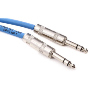
The ¼ Inch connector was originally known as the phone jack or phone connector because it was developed for use with telephone switchboards. ¼ Inch connectors are now used in the professional audio industry to transmit analog signals from sources such as musical instruments and mixing consoles.
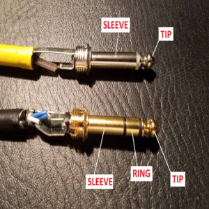
The two most common versions of these connectors are TS and TRS, the T stands for “tip”, R stands for “ring”, and S stands for “sleeve”.
- TRS (Balanced) – With TRS plugs the conventional wiring configuration is T=Tip (+Signal), R=Ring (-Signal), and S=Sleeve (Ground/Shield), this provides the ability to transmit balanced audio signals.
- TRS (Stereo) – With TRS Stereo plugs, the connectors are wired in stereo fo tradition studio headphones.
- TS (Unbalanced) – With TS plugs the conventional wiring is T=Tip (+Signal) and S=Sleeve (Ground/Shield), these plugs can only carry unbalanced audio signals.
The connector comes in both a TS and TRS design for balanced audio signals, as well as male and female to connect the instrument to an amplifier.
3.5mm Connector
Complete Guide To Analog Input Connectors
The 3.5mm connector is also referred to as a “miniature or mini plug” because it is essentially the half-size version of a ¼ inch connector, it is also sometimes called a 1/8-inch connector.
In most cases with the 3.5mm connector, a TS or TRS connector does not determine whether it’s balanced or unbalanced but determines whether it’s being used for a stereo or mono application. Most of the time these cables are carrying unbalanced signals, if the cable has TRS connectors it’s transmitting a stereo signal, if the cable has TS connectors it’s transmitting a mono signal.
The most common wiring configuration for a cable with TRS connectors transmitting a stereo signal is T=Tip (+Left Signal), R=Ring (+Right Signal), and S=Sleeve (Ground/Shield).
In the case of the cable with TS connectors, it would have the following connections: T=Tip (+Signal), and S=Sleeve (Ground/Shield).

Euroblock/Phoenix Connector
Complete Guide To Analog Input Connectors
Euroblock is a solderless connector that uses screw terminals to clamp connection wires. After the wires are installed, the assembly is plugged into a corresponding outlet on the electronic device. Euroblocks are more convenient than the terminal blocks they replace because signal cables can quickly be disconnected or connected to electronics, rather than unscrewing and rewiring each wire.


Can You Connect An Unbalanced Connector To A Balanced Input?
Complete Guide To Analog Input Connectors
While it is best practice to connect a balanced analog output to a balanced analog input it is possible to connect an unbalanced output to a balanced input. It may require a little bit of work to do it properly.
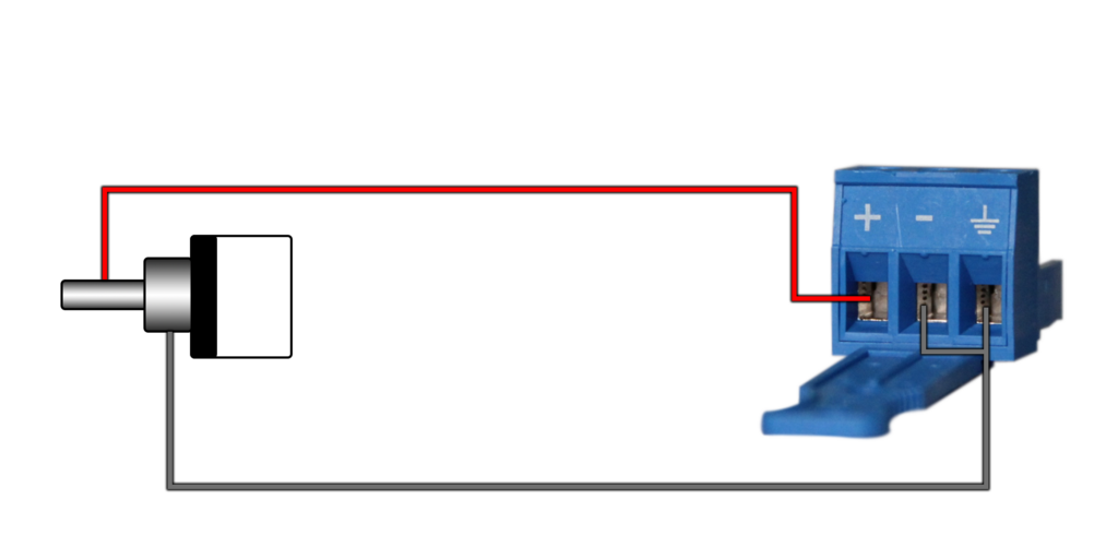
The first step requires cutting one end of the unbalanced cable. For RCA connectors you typically get a Red, White, or Black, and a braided shield conductor. The Red is your Right + analog signal. The White or Black is your Left + signal. The braded shield conductor is the Ground.
Next, you wire the Red Right + from the wire to the + of the balanced connector. Then, connect the shield/ground to the ground of the balanced connector. Then simply make a jumper that connects the ground to the negative (-) pin of the balanced connector. This is now your Right analog input. To do the left analog, you repeat the process and wire the White or Black Left + from the wire to the + of the balanced connector. Then, connect the shield/ground to the ground of the balanced connector. Then simply make a jumper that connects the ground to the negative (-) pin of the balanced connector. This is now your Left analog input. Below you will see a simple diagram showing this:
Can You Connect An balanced Connector To A Unbalanced Input?
Complete Guide To Analog Input Connectors
This can be done but it requires a little more attention to the details of how balanced output circuit is constructed. In some cases, it may require referencing the specification sheet or owner’s manual of the output device to determine the proper wiring configuration.
Because an unbalanced connection only requires the + Signal and Ground/Shield conductors we need to determine what we will do with the – Signal conductor coming from the balanced output, essentially there are two options which are listed below.
- Connect the -Signal conductor to the Ground/Shield conductor
- Leave the -Signal conductor floating (disconnected) at the unbalanced input.
If the balanced output has a transformer tying the -Signal to the Ground/Shield will be required.
The Conclusion
Complete Guide To Analog Input Connectors
We hope this guide has answered any questions, provided useful information, and added to you knowledge of audio connectors. If you have any questions or feedback regarding audio connectors, feel free to leave a comment or reach out to us on our social media channels below.
Enjoy!
Want more LEA content delivered directly to your inbox? Enter your email address below to be subscribed to our monthly newsletter and keep up with all of the latest news and content from LEA Professional.